The only possible option is the later GWM/Haval version of the 4G69 engine as found in the Steed Utes from about 2021 that may have 10.5:1 pistons in them but may also have smaller combustion chambers in the head accounting for the raised compression. Have yet to find a pic of the pistons to verify if it is the pistons that are flat tops to account for a 10.5:1 CR. If so these should be dirt cheap to buy on Aliexpress (not from a stealership). Several Chinese carmakers still use the 4G69 block and internals with a revised head (non-mivec, non performance). Do your research!
You are using an out of date browser. It may not display this or other websites correctly.
You should upgrade or use an alternative browser.
You should upgrade or use an alternative browser.
4g69 cylinder head upgrade options
- Thread starter Radical_Ralliart
- Start date
Radical_Ralliart
Member
Pistons and comp ratio aside, i’ve looked into some differing opinions on port and polishing the cylinder head. I probably wouldn’t polish or have a golf ball texture on the intake ports at all, but what about polishing the exhaust ports to a mirror finish? Most people seem to think its not a bad idea.
Also, i’m gonna go ahead on getting rpw 4-1 41mm headers. I believe it’ll be the best option for flow out of the headers i’ve seen, i will be getting the fattest resonator i can get to eliminate the beehive noises though
Also, i’m gonna go ahead on getting rpw 4-1 41mm headers. I believe it’ll be the best option for flow out of the headers i’ve seen, i will be getting the fattest resonator i can get to eliminate the beehive noises though
Knife edge the dividers in favour of the more shrouded exhaust valve. Same on intake side but these are already symmetrical.
Smooth out the casting marks and call it done. Do not try to increase the size of the ports - they are big enough already.
If you have loads of spare cash, get a polish for that placebo effect.
While you have the head off, think about shaving it to raise the compression if you are not going to put high compression pistons in it. Any extra C.R is gold.
Radical_Ralliart
Member
Just wanted to go back to the cam specs you gave earlier, did you measure these specs out yourself or is this available info on a mitsu rebuild manual?
Opens Closes Duration Lift Center
Intake Lo 10 BTDC 42 ABDC 232 4.094 106
Intake Mid 12 BTDC 44 ABDC 236 9.344 106
Intake Hi 24 BTDC 68 ABDC 272 10.3854 112
Exhaust 58 BBDC 18 ATDC 256 9.9266 110
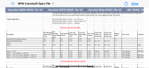
Another question i’d have for rpw is why tf are their stock cam specs so different to the specs you’ve given? Not just that but going off their stage 1 cam, it looks like it has LESS duration and lift on the high lobe cam for some reason, is this possibly to make the 9.5:1 comp ratio combustion more efficient?

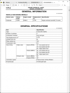
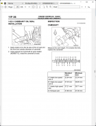
Simple - the cam specs I quoted are JDM (all AU models) from the service manual and are "at the cam". I checked the lift to confirm that the cam indeed has 3 different lifts for the 3 different intake lobes (not 2 as RPW quotes). Some U.S company started the error in trying to look knowledgeable without ever seeing a 4G69 cam and fabricated some B.S figures to publish. Also RPW looks like it is quoting the durations and lift at 1mm or 50 thou lift, not "at the cam" which does not take into account the rocker clearance therefore are larger.
2 pages out of the service manual: 1st pages shows duration of the 3 intake cam lobes, 2nd page shows the 3 different lobe heights from which you can see that there are 3 different lifts. I cannot say what the USA car models with 4G69 engines came out with but suspect it is the same since they have the same output power. Welcome to the world of misinformation called the Internet!


2 pages out of the service manual: 1st pages shows duration of the 3 intake cam lobes, 2nd page shows the 3 different lobe heights from which you can see that there are 3 different lifts. I cannot say what the USA car models with 4G69 engines came out with but suspect it is the same since they have the same output power. Welcome to the world of misinformation called the Internet!


Radical_Ralliart
Member
How would i work out the valve overlap on this engine? I wanna try and work out what could be adjusted on a custom billet cam for it, obviously would increase the miserable lift on the low-lift lobe, but i wanna work out if increasing the valve overlap on the high lobe and exhaust lobe would make more power
To work out the overlap, all you need is the duration and centerline of the lobes and an understanding of cam dynamics.
For the intake low speed lobes I would make the lift of the lower lobe the same as the higher lobe and increase both by a small amount aiming for a lift (at the cam) of 9.8mm . I would set the centerline of both low speed lobes to 108 and increase the duration to 240 degrees. If you go higher than this, a hole in the torque curve will appear around 3000rpm so you will lose power by going bigger. Sometimes less is more.
For the high speed cam, I would leave the duration and centerline alone but lobe height needs to be increased to keep it 0.14mm less than the low speed lobes new height. This is for mechanical reasons. The valvetrain configuration is intolerant to arbitrary cam specs as everything must work together to enable the lobe switch.
The exhaust lobes are pretty good on duration, lift and centerline already. I would be reluctant to alter too much here. Maybe just increase the lift a fraction.
If you want a preview of what it would be like to have much bigger low speed cam lobes, apply a constant 12V source to the oil solenoid that activates the high speed cam and take it for a drive.....
Radical_Ralliart
Member
Have you ever driven your outlander with high lobes constantly on? Interested to know if it’d have some lump to it in idleTo work out the overlap, all you need is the duration and centerline of the lobes and an understanding of cam dynamics.
For the intake low speed lobes I would make the lift of the lower lobe the same as the higher lobe and increase both by a small amount aiming for a lift (at the cam) of 9.8mm . I would set the centerline of both low speed lobes to 108 and increase the duration to 240 degrees. If you go higher than this, a hole in the torque curve will appear around 3000rpm so you will lose power by going bigger. Sometimes less is more.
For the high speed cam, I would leave the duration and centerline alone but lobe height needs to be increased to keep it 0.14mm less than the low speed lobes new height. This is for mechanical reasons. The valvetrain configuration is intolerant to arbitrary cam specs as everything must work together to enable the lobe switch.
The exhaust lobes are pretty good on duration, lift and centerline already. I would be reluctant to alter too much here. Maybe just increase the lift a fraction.
If you want a preview of what it would be like to have much bigger low speed cam lobes, apply a constant 12V source to the oil solenoid that activates the high speed cam and take it for a drive.....
No, but you can tell me when you do it. Not hard to hook up a 12V wire straight to the solenoid for a test. It will of course, have an adverse effect on the tuning since the high cam knocks the compression ratio down so without compensating for this by advancing the ign timing plus adjusting the fuel, you will see a significant power drop below 3500rpm but it might have a bit of a lumpy idle as much as a modern fuel injected car can have - the ign timing is constantly being adjusted to maintain a solid idle so it fights against any cam loping. One would have to reduce the range that the ign timing can move if one wants a lumpy, ricey idle or you could record a hot 4 with a lumpy idle and just play that on the stereo....
