I know all of you have been dreaming, now there is no excuse
Unfortunately at the moment there are no step by step pics (sorry) as mine was a trial and error process, if you do the the conversion plz take some pics as you do it and let me know thnx.
DIY climate control:
So, you’ve decided that you want to be cool and have climate control, well sit back and relax, let me take you through the process. Firstly; if your not confident cutting into your dash loom or wielding a soldering iron. This isn’t for you; go do some simpler mods till you gain some confidence. This guide relies upon you having "JDM" air con, if you have a full fuse box for the air-con like engine bay fuse box near the battery then you have "JDM" air-con. I haven't tried any of the other styles of air con. At present i believe there are up to 25 different combos of air con systems, getting your pipe work to fit MAY be a case of trial and error.
Guide to my guide:
CC means Climate Control (in case you couldn’t work that out :lol")
**~~~ ** Are my top tips (following them may make your life easier and stop your interior smelling of coolant like mine does)
Parts:
From either Evo 4/5/6 (cp9a chassis) or FTO
Blower box
Air con condenser box
Heater core box
Control unit (This will only work with an FTO or EVO control unit - the Magna/Verada one has a different pinout for the aircon-on button)
Dash loom
External temp sensor
From Evo 4/5/6
Air con fascia plate
Other:
One M6 X 25mm metric fine bolt
Tarp/plastic drop sheet (to protect your interior)
Coolant
Electrical tape or zip ties
** Before you start installing you will need to have your air con degassed, so it’s not the greatest idea to be doing this in the middle of summer. **
Tools:
Socket set with decent length extensions
Philips head screw driver
Flat head screw driver
Hobby knife or Stanley knife
Wire snips
Wire strippers
Soldering iron
Heat-shrink
Heat gun (You could use a lighter, but flame + main wiring harness = not the greatest idea)
Hammer
Separating the CC loom from the donor dash loom:
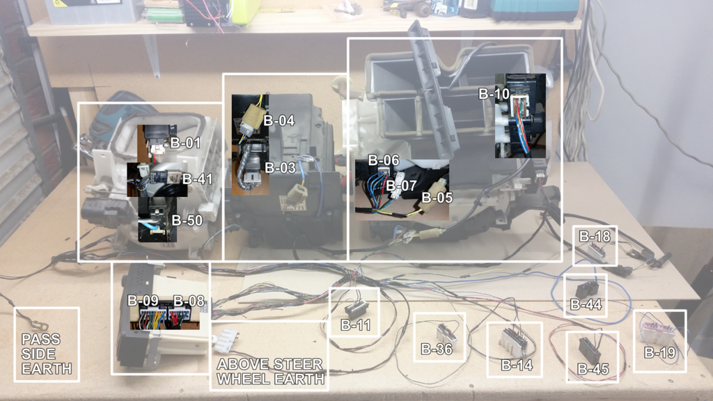
1. Set out the boxes, going from left to right; blower, air con, heater core.
2. Identify and label which plugs go into the various servos and motors on the boxes, and the control unit.
3. This makes life easier to trace cables once the loom is apart.
4. Remove the tape holding the dash loom together.
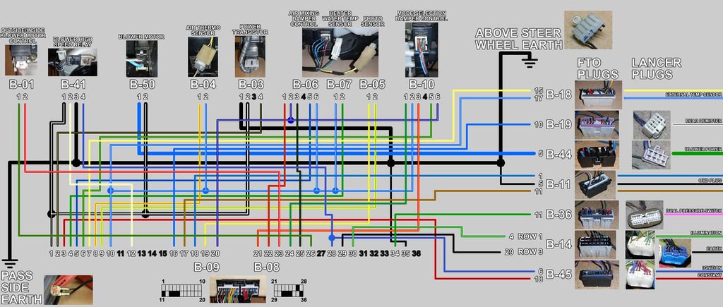
5. Cut appropriate wires as below:
**Colour code; like the workshop manual the first colour represents the main wire and the second colour represents the trace colour **
In the loom, do not cut (well done ces):
Heater box (mode selection motor)
Green-blue, Red-yellow, Blue-yellow, Green-orange, Blue-white
Heater box (heater water temp sensor)
Green, Blue-white
Heater box (hot/cold mixer)
Blue-yellow, Blue-black, Blue-white, Red-green, Blue-green
Air con box (air thermo sensor)
Yellow-red, Blue-white
Blower high-speed relay
White-yellow
Power Transistor
Black-white, Black-yellow
To be spliced into the car dash loom using FTO loom:
Constant power
Join the red-black wire (car side) to the red black wire (CC side)
Switched ignition
Join the blue-black wire (car side) to the blue-red wire (CC side)
Ground
Terminate the black wires to the chassis with crimp a connector
Demister
Join the white-black wire (car side) to the blue wire (CC side)
Illumination
Join the green white-wire (car side) to the green white wire (CC side)
Dual pressure switch
Join the pink wire (car side) to the green wire (CC side)
Blower motor
Join the thick green wire (car side) to the thick blue wire (CC side)
Outside temp sensor
You’ll need to extend the yellow and blue white (both in the CC loom) about 2.2m, enough for the wires to go through the firewall grommet on the passenger side, down the passenger side of the engine bay (following the engine bay loom) to the radiator support where the outside temp sensor will plug in to it.
To be spliced into the car dash loom (EVO loom):
Constant power
Join the red black (car side) to the red black-wire (CC side)
Switched ignition
Join the blue-red wire (car side) to the blue-red wire (CC side)
Ground
Terminate the black wires to the chassis with crimp a connector
Demister
Join the white-black wire (car side) to the white-black (CC side)
Illumination
Join the green-white wire (car side) to the green-white wire (CC side)* (will double check)
Dual pressure switch
Join the pink wire (car side) to the pink wire (CC side)* (will double check)
Blower motor
Join the thick green wire (car side) to the thick green wire (CC side)
Not needed:
Photo sensor
There is another sensor called the photo sensor, this mounts in the dash near the bottom of the windscreen. The photo sensor is used to control the temp, for eg. while driving in and out of the sunshine, it compensate for those quick changes that you feel on your body and not entirely the actual temp inside the car
So if your car is set to 25deg in the morning, when the day gets hotter the sensor will tell the unit that its a hot day and slowly turn to compensate for the extra heat from outside. (Thanks Mike) The photo sensor uses two wires Yellow-white and Yellow-green.
Diagnostics
There are two wires (Brown-red, Blue-green), which go to the OBD2 port, I didn’t wire them in, the few other people who have done this before, they didn’t either.
Remove dash:
Disconnect the battery
Thanks to ozz:
Removal of Air Con boxes:
1. Drain the coolant from the system
2. Disconnect the two hoses that connect the heater core to the engine block.
3. Disconnect the two air con hard lines from the air con condenser
4. Unplug the blower motor and manual control box
5. Cut the manual control cables
6. Undo the eight (four on top and four underneath) 12mm nuts holding the three boxes in
7. Remove the top and bottom ducts off the heater core box. They just pop off.
8. Remove the condenser box first, then the blower box and finally the heater box.
**To make it easier to get the heater box out, the center pillars that hold radio etc, the left one can be remove; two bolts top and bottom and a single bolt holding the fuel pump relay **
**Place a tarp/plastic drop sheet in the passenger foot well to catch any spills of coolant or air con oil/dye**
Installation time:
1. Splice the climate control loom into the dash loom, and heat shrink all joints to isolate them (remember to slide the heat shrink on one of the wires before you solder the joint) as per:
Constant power
Join the yellow (generally from HU) wire (car side) to the red black wire (CC side)
Switched ignition
Join the blue-black wire (car side) to the blue-red wire (CC side)
Ground
Terminate the black wires to the chassis with crimp a connector
Demister
Join the white-black wire (car side) to the blue wire (CC side)
Illumination
Join the green white-wire (car side) to the green white wire (CC side)
Dual pressure switch
Join the green wire (car side) to the pink wire (CC side)
Blower motor
Join the thick green wire (car side) to the thick blue wire (CC side)
Outside temp sensor
You’ll need to extend the yellow and blue white (both in the CC loom) about 2.2m, enough for the wires to go through the firewall grommet on the passenger side, down the passenger side of the engine bay (following the engine bay loom) to the radiator support where the outside temp sensor will plug in to it.
2. Before you start to put the new boxes in the car, plug in all the motors, sensors and control unit in to your new loom.
3. Re-connect the battery and turn the ignition to ON – do not start the engine
4. The control unit should now light up and the motors move.
5. Go through all the settings and make sure all the motors/servos work. If they don’t now is the time to go back and check your solder connections etc.
6. If everything works, yay for you, you’re as awesome as me!
7. Unplug everything and install the three boxes, Installation of the boxes is the reverse of removal (funny that)
8. The heater box goes in first,
9. Followed by the blower box
10. And finally the air con box
11. If you removed the center metal pillar, bolt it back on
12. Re-attach the top and bottom ducts to the heater box
13. Plug the new climate control loom into the various motors and sensors
14. Neaten up the loom with tape or cable ties, make sure there is enough slack to plug the control unit back in. Also make sure that the loom will not snag on any of the moving parts of the boxes.
15. Re-attach the heater hoses to the heater core and re-fill the coolant system
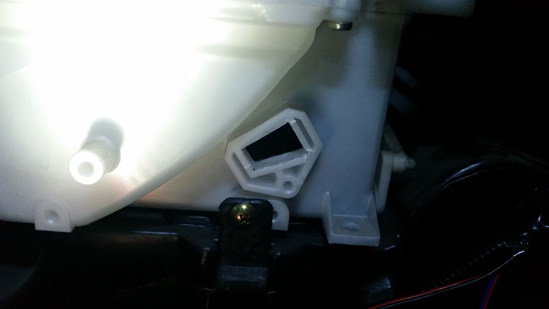
16. Re-attach the air con hard lines; this is where you may need the M6 X 25 metric fine bolt to attach the thicker of the hard lines to the condenser.
17. The outside air temp sensor mounts in front of the radiator support, on the bonnet latch. Hammer the lips flat so the bracket slides under the latch mechanism and bolts in
18. Putting the dash back in, is once again the reverse of removing it.
Mounting the control unit
How you mount the control unit is up to you. If you are really lucky you can find the OEM brackets of a evo. Failing that the best way to do it is to make a pair of brackets that mount to the back of the unit and screw to the existing manual control mounting locations.
Finally put the new CC fascia trim on, and go get your air con re-gassed.
Congratulations, you’re now as cool as me coz you have Climate Control, or you’re just super jelly. If you have any questions just PM me.
For those of you who are technically minded and aren't afraid to read tech manuals. This is the workshop manuals for the evo 4 and 5.
https://drive.google.com/folderview?id= ... sp=sharing
Unfortunately at the moment there are no step by step pics (sorry) as mine was a trial and error process, if you do the the conversion plz take some pics as you do it and let me know thnx.
DIY climate control:
So, you’ve decided that you want to be cool and have climate control, well sit back and relax, let me take you through the process. Firstly; if your not confident cutting into your dash loom or wielding a soldering iron. This isn’t for you; go do some simpler mods till you gain some confidence. This guide relies upon you having "JDM" air con, if you have a full fuse box for the air-con like engine bay fuse box near the battery then you have "JDM" air-con. I haven't tried any of the other styles of air con. At present i believe there are up to 25 different combos of air con systems, getting your pipe work to fit MAY be a case of trial and error.
Guide to my guide:
CC means Climate Control (in case you couldn’t work that out :lol
**~~~ ** Are my top tips (following them may make your life easier and stop your interior smelling of coolant like mine does)
Parts:
From either Evo 4/5/6 (cp9a chassis) or FTO
Blower box
Air con condenser box
Heater core box
Control unit (This will only work with an FTO or EVO control unit - the Magna/Verada one has a different pinout for the aircon-on button)
Dash loom
External temp sensor
From Evo 4/5/6
Air con fascia plate
Other:
One M6 X 25mm metric fine bolt
Tarp/plastic drop sheet (to protect your interior)
Coolant
Electrical tape or zip ties
** Before you start installing you will need to have your air con degassed, so it’s not the greatest idea to be doing this in the middle of summer. **
Tools:
Socket set with decent length extensions
Philips head screw driver
Flat head screw driver
Hobby knife or Stanley knife
Wire snips
Wire strippers
Soldering iron
Heat-shrink
Heat gun (You could use a lighter, but flame + main wiring harness = not the greatest idea)
Hammer
Separating the CC loom from the donor dash loom:
1. Set out the boxes, going from left to right; blower, air con, heater core.
2. Identify and label which plugs go into the various servos and motors on the boxes, and the control unit.
3. This makes life easier to trace cables once the loom is apart.
4. Remove the tape holding the dash loom together.
5. Cut appropriate wires as below:
**Colour code; like the workshop manual the first colour represents the main wire and the second colour represents the trace colour **
In the loom, do not cut (well done ces):
Heater box (mode selection motor)
Green-blue, Red-yellow, Blue-yellow, Green-orange, Blue-white
Heater box (heater water temp sensor)
Green, Blue-white
Heater box (hot/cold mixer)
Blue-yellow, Blue-black, Blue-white, Red-green, Blue-green
Air con box (air thermo sensor)
Yellow-red, Blue-white
Blower high-speed relay
White-yellow
Power Transistor
Black-white, Black-yellow
To be spliced into the car dash loom using FTO loom:
Constant power
Join the red-black wire (car side) to the red black wire (CC side)
Switched ignition
Join the blue-black wire (car side) to the blue-red wire (CC side)
Ground
Terminate the black wires to the chassis with crimp a connector
Demister
Join the white-black wire (car side) to the blue wire (CC side)
Illumination
Join the green white-wire (car side) to the green white wire (CC side)
Dual pressure switch
Join the pink wire (car side) to the green wire (CC side)
Blower motor
Join the thick green wire (car side) to the thick blue wire (CC side)
Outside temp sensor
You’ll need to extend the yellow and blue white (both in the CC loom) about 2.2m, enough for the wires to go through the firewall grommet on the passenger side, down the passenger side of the engine bay (following the engine bay loom) to the radiator support where the outside temp sensor will plug in to it.
To be spliced into the car dash loom (EVO loom):
Constant power
Join the red black (car side) to the red black-wire (CC side)
Switched ignition
Join the blue-red wire (car side) to the blue-red wire (CC side)
Ground
Terminate the black wires to the chassis with crimp a connector
Demister
Join the white-black wire (car side) to the white-black (CC side)
Illumination
Join the green-white wire (car side) to the green-white wire (CC side)* (will double check)
Dual pressure switch
Join the pink wire (car side) to the pink wire (CC side)* (will double check)
Blower motor
Join the thick green wire (car side) to the thick green wire (CC side)
Not needed:
Photo sensor
There is another sensor called the photo sensor, this mounts in the dash near the bottom of the windscreen. The photo sensor is used to control the temp, for eg. while driving in and out of the sunshine, it compensate for those quick changes that you feel on your body and not entirely the actual temp inside the car
So if your car is set to 25deg in the morning, when the day gets hotter the sensor will tell the unit that its a hot day and slowly turn to compensate for the extra heat from outside. (Thanks Mike) The photo sensor uses two wires Yellow-white and Yellow-green.
Diagnostics
There are two wires (Brown-red, Blue-green), which go to the OBD2 port, I didn’t wire them in, the few other people who have done this before, they didn’t either.
Remove dash:
Disconnect the battery
Thanks to ozz:
ozz said:Pics detail the locations of the bolts and screws that hold the dash in.
Here's a brief write up on my procedure to do the interior dash in a CE Lancer or Mirage. It's probably applicable to other models too I just don't know which ones have this dash.
Procedure to REMOVE DASH:
TIP- For each bunch of screws/tabs you take out put them in a small plastic bag and label it in conjunction with the part it came off. Saves a lot of hassle later on
1. SIDE A/C VENTS: should pull straight out with a little muscle (try to apply even pressure with both hands pulling either side or top/bottom of a vent).
2. A/C CONTROLS SURROUND: pull's straight out also (have to disconnect the plugs and 4 screws holding the dials onto the dash).
3. STEREO SURROUND: pull's straight out after you take out the ashtray. Disconnect the cig lighter.
4. GLOVE BOX: with a little effort you can get the tabs over the ridge things that stop it opening to the ground. This lets it drop down so you can easily access the screws that hold it on.
5. PANEL UNDER STEERING COLUMN: There are 4 screws holding this on. Also has the variable dial for your speedo cluster lights (just disconnect the plug when you see it).
6. STEERING COLUMN: 3 screws. Need a long screwdriver to get to one of them. Should pull apart from top piece after screws removed.
7. DASH CLUSTER SURROUND: 2 screws. Then pulls out.
8. DASH CLUSTER: 5 screws (I think, easy enough to see though). Pulls out off 2 plugs in the back.
9. CENTER CONSOLE (BACK): 2 screws down in the storage part. Un-clips out of the front piece.
10. CENTER CONSOLE (FRONT): 6 screws. 2 under where the back piece was, 2 behind the Stereo Surround & 1 on each side under the foot wells at the front.
OK, so that's all the little parts you need to get off before taking out the entire rest of the dash. Sorry if I've missed 1 or 2 screws/bolts, they should be easy enough to find though
Should have remaining: Main piece (runs along the windshield with vents in it), Semi-soft top insert piece (has the indent tray type thing in it), the surrounds of the center a/c vents/controls and cluster surround (has a little coin thing and a square switch panel in it also).
This should all be able to come out as one piece and then you can pull that apart further if need be.
MAIN DASH:
Where you took out the side vents there is a bolt down the back in each vent cavity.
Another bolt far left down in the foot well.
Where the Glove Box used to be there are 3 screws here and 1 bolt.
Where the Stereo Surround came from there are 2 bolts (might need to disconnect an Earth wire here if there is one). 1 screw at the top.
Under the Steering Column there is a screw on the far right (behind the Bonnet Release sort of), and I think there's one to the left of the column too.
Another bolt is behind where the Dash Cluster was.
Now the dash should be able to be pulled free. I got mine loose and pulled it out through the passenger side door. It's a bit tricky but it'll come out.
Once out you can pull it apart further to paint/cover individual parts. I'll leave that to you as it's simple to do.
Here's some pictures where I've roughly marked out the location's of the screws/bolts. Hope they help.


Props to -Owen for the original of this.
Removal of Air Con boxes:
1. Drain the coolant from the system
2. Disconnect the two hoses that connect the heater core to the engine block.
3. Disconnect the two air con hard lines from the air con condenser
4. Unplug the blower motor and manual control box
5. Cut the manual control cables
6. Undo the eight (four on top and four underneath) 12mm nuts holding the three boxes in
7. Remove the top and bottom ducts off the heater core box. They just pop off.
8. Remove the condenser box first, then the blower box and finally the heater box.
**To make it easier to get the heater box out, the center pillars that hold radio etc, the left one can be remove; two bolts top and bottom and a single bolt holding the fuel pump relay **
**Place a tarp/plastic drop sheet in the passenger foot well to catch any spills of coolant or air con oil/dye**
Installation time:
1. Splice the climate control loom into the dash loom, and heat shrink all joints to isolate them (remember to slide the heat shrink on one of the wires before you solder the joint) as per:
Constant power
Join the yellow (generally from HU) wire (car side) to the red black wire (CC side)
Switched ignition
Join the blue-black wire (car side) to the blue-red wire (CC side)
Ground
Terminate the black wires to the chassis with crimp a connector
Demister
Join the white-black wire (car side) to the blue wire (CC side)
Illumination
Join the green white-wire (car side) to the green white wire (CC side)
Dual pressure switch
Join the green wire (car side) to the pink wire (CC side)
Blower motor
Join the thick green wire (car side) to the thick blue wire (CC side)
Outside temp sensor
You’ll need to extend the yellow and blue white (both in the CC loom) about 2.2m, enough for the wires to go through the firewall grommet on the passenger side, down the passenger side of the engine bay (following the engine bay loom) to the radiator support where the outside temp sensor will plug in to it.
2. Before you start to put the new boxes in the car, plug in all the motors, sensors and control unit in to your new loom.
3. Re-connect the battery and turn the ignition to ON – do not start the engine
4. The control unit should now light up and the motors move.
5. Go through all the settings and make sure all the motors/servos work. If they don’t now is the time to go back and check your solder connections etc.
6. If everything works, yay for you, you’re as awesome as me!
7. Unplug everything and install the three boxes, Installation of the boxes is the reverse of removal (funny that)
8. The heater box goes in first,
9. Followed by the blower box
10. And finally the air con box
11. If you removed the center metal pillar, bolt it back on
12. Re-attach the top and bottom ducts to the heater box
13. Plug the new climate control loom into the various motors and sensors
14. Neaten up the loom with tape or cable ties, make sure there is enough slack to plug the control unit back in. Also make sure that the loom will not snag on any of the moving parts of the boxes.
15. Re-attach the heater hoses to the heater core and re-fill the coolant system
16. Re-attach the air con hard lines; this is where you may need the M6 X 25 metric fine bolt to attach the thicker of the hard lines to the condenser.
17. The outside air temp sensor mounts in front of the radiator support, on the bonnet latch. Hammer the lips flat so the bracket slides under the latch mechanism and bolts in
18. Putting the dash back in, is once again the reverse of removing it.
Mounting the control unit
How you mount the control unit is up to you. If you are really lucky you can find the OEM brackets of a evo. Failing that the best way to do it is to make a pair of brackets that mount to the back of the unit and screw to the existing manual control mounting locations.
Finally put the new CC fascia trim on, and go get your air con re-gassed.
Congratulations, you’re now as cool as me coz you have Climate Control, or you’re just super jelly. If you have any questions just PM me.
For those of you who are technically minded and aren't afraid to read tech manuals. This is the workshop manuals for the evo 4 and 5.
https://drive.google.com/folderview?id= ... sp=sharing